The Science Behind Metal Slitting
Metal slitting is a precision converting process that transforms wide metal coils into narrower strips for further processing or end-use applications. In industries such as automotive, construction, and appliance manufacturing, maintaining tight tolerances and superior edge quality is critical. A high-performance slitting line must deliver consistent accuracy in width, flatness, and edge condition, all while operating at high speeds. The quality of the slit edge directly affects downstream forming, welding, and coating processes. Therefore, understanding the engineering principles behind precision metal slitting is essential to optimizing performance, minimizing scrap, and extending blade life.
Overview of Slitting Methods in Metal Processing
While several cutting techniques are used across materials, in metal applications three core methods are relevant:
2.1. Shear Slitting (Most Common in Metal Lines)
In shear slitting, a top rotary knife works against a bottom knife in a scissor-like action, creating a clean, burr-free edge. This method is preferred for most metallic coils due to its precision and repeatability. Shear slitting can be further divided into:
- Wrap Shear Slitting: The web wraps around the bottom slitter band, and the cut point can occur anywhere within the wrap.
- Tangential Shear Slitting: The web is tangent to the bottom band, with the cut point limited to a small area where the web contacts the top of the bottom band.
2.2. Crush Slitting
Crush slitting involves pressing a rotating blade against a hardened anvil roll. It is generally unsuitable for metal due to the required force and the risk of deformation, but can be used for thin foils or soft alloys in low-speed applications.
2.3. Razor or Laser Slitting
Used mainly in nonmetallic materials; however, hybrid metal–polymer laminates may occasionally employ razor-assisted systems.
In metal slitting, shear slitting remains the gold standard, ensuring mechanical precision and repeatability.
Understanding Shear Geometry: Depth, Overlap, and Cant Angle
3.1. Overlap Depth
Overlap is the vertical penetration of the top blade into the bottom blade. For metallic coils, optimal overlap typically ranges from 0.02 mm to 0.10 mm, depending on the material thickness and hardness.
- Too deep → excessive burr formation and higher tool wear.
- Too shallow → incomplete cuts or tearing.
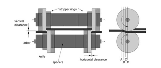
3.2. Cut Point Position
The ideal cut point must be slightly inside the wrap zone of the lower knife. This ensures the material is supported throughout the shearing process, preventing deflection and distortion.
3.3. Cant (Shear) Angle
Cant (Shear) Angle
The cant (or shear) angle is the angular relationship between the upper slitter blade and the lower band. It allows the blades to engage progressively, producing a true shearing action instead of tearing or plowing through the material.
The cant angle (Θ) can be measured using the relationship:
where A is the measured gap (between the top blade and bottom band behind the cut point), and B is the chord length.
As the chord increases, the measured gap becomes larger for the same angle. Reference tables are often used to determine the correct gap for a given chord length. A steeper cant angle provides faster cutting but also increases blade wear. Therefore, the optimal cant angle is the minimum angle required to reliably slit the web. It is also essential to ensure that the cant angle is always positive, preventing blade damage or material distortion.
In practice:
The cant angle is the angular offset between the top and bottom knives, providing the “scissoring” motion necessary for clean shear.
- Recommended range for metals: 0.25°–0.75°
- Note: Larger angles accelerate wear and may distort thin coils.
Proper calibration of these parameters ensures a consistent, clean shear without tearing the metal.
Side Load, Web Tension, and Speed Synchronization
In high-speed metal coil slitting, blade side loading and web tension control are as important as blade sharpness.
- Side Load: The lateral pressure keeping the upper and lower knives engaged. For most setups, this should be as light as possible while maintaining traction.
- Tension Control: Uneven web tension leads to camber, edge waves, or telescoping of slit coils. Tension must remain constant across the entire width.
- Slitter Speed vs. Coil Speed: The knife rotation should operate at 3–5% overspeed relative to line speed to simulate the scissor shearing effect, preventing edge tearing.
- Material, Blade Profile
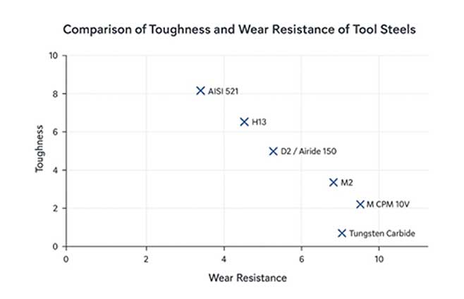
5.1. Blade Materials
Different alloys are used depending on production demands:
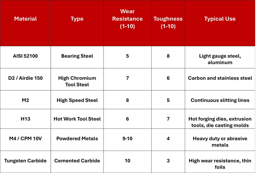
- AISI 52100: High wear, moderate toughness
- D2 / Airdie 150: Very high wear, low-moderate toughness
- M2: High wear, moderate toughness
- M4 / CPM 10V: Very high wear, moderate-high toughness (due to powder metallurgy)
- H13: Moderate wear, high toughness
- Tungsten Carbide: Extremely high wear, very low toughness (brittle)
5.2. Blade Profile and Edge Finish
A properly ground blade must have a mirror-polished surface with no burrs or grinding marks.
- Primary angle: 45°–60° for most metals.
- Compound bevels: reduce web distortion and increase tip strength.
- Superfinishing (Ra ≤ 0.1 µm) extends blade life and improves edge quality.
Common Cutting Defects and Troubleshooting
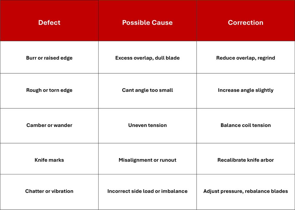
Understanding these root causes allows operators to diagnose and correct issues in real time, reducing downtime and scrap.
- Precision Control Defines Performance
In modern coil processing, metal slitting is both an art and a science. Every variable from blade metallurgy to cant angle, side pressure, and web speed must operate in harmony.
A well-calibrated shear slitting setup delivers:
- Superior edge quality with minimal burrs.
- Longer blade life and fewer regrinds.
- Reduced scrap and downtime.
At LOTOS, we continuously innovate to optimize slitting accuracy through advanced blade technology, precision engineering, and automated monitoring systems. Our commitment to excellence ensures consistent quality, higher productivity, and lower operational costs across global manufacturing lines.