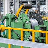
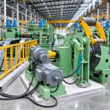
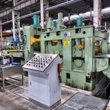
Scrap Winding Machine for Slitting Lines
In coil slitting operations, the removal of edge trim is an unavoidable part of the process. Each time a master coil is cut to the required strip widths, the side edges are trimmed to achieve accurate dimensions and clean edge quality. This trimmed material, known as scrap or edge trim, is a continuous narrow strip that must be collected safely and efficiently.
A scrap winding machine, also called a scrap winder or edge trim coiler, is the dedicated unit that winds this continuous strip into compact, manageable coils. Without a reliable scrap handling system, edge trim can tangle, accumulate in the pit, damage equipment, and create serious safety hazards for operators.
What Is a Scrap Winding Machine?
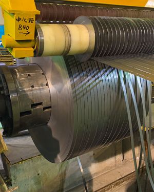
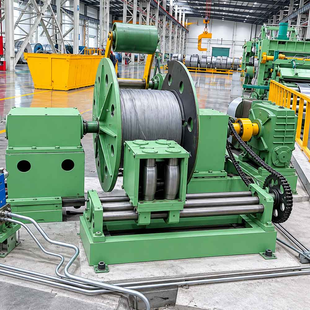
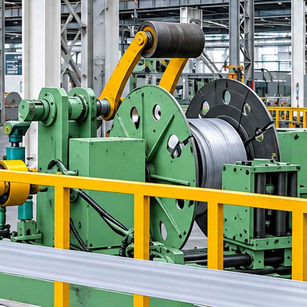
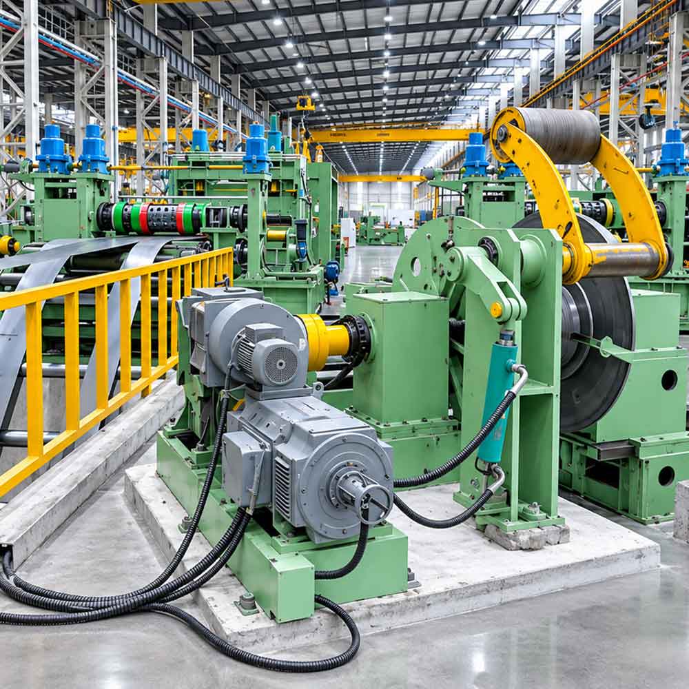
A scrap winding machine is a motor driven winding device installed at the exit side of the slitter head. It continuously pulls the trimmed edge strips away from the slitting section and winds them onto a rotating mandrel or drum, forming a tight coil that can be removed and transported easily.
Compared with alternative methods such as scrap choppers or manual collection, a scrap winder is particularly suitable for processing long, continuous trim strips of medium to heavy gauge material. It keeps the working area clean, reduces handling risks, and facilitates scrap recycling.
Why a Scrap Winding Machine Is Necessary
Functions in the Slitting Process
- Continuous removal of edge trim from the slitter head without interrupting production.
- Prevention of scrap tangling in the slitter pit or around the knife shafts.
- Safe handling of sharp edged scrap, minimizing the risk of operator injury.
- Compact scrap coils that reduce storage volume and simplify transport and recycling.
- Stable slitting conditions, since controlled trim take up avoids interference with the main strip.
Working Principle
The scrap winding machine operates in synchronization with the slitting line. As the master coil passes through the slitter head, the circular knives cut away the side edges. The trim strips are guided through a scrap deflector or guide, then fed directly to the winding mandrel.
- Trim separation: The slitter knives cut the edge strips from the main strip.
- Guiding: Scrap guides or deflectors direct the trim toward the winder, preventing contact with the slitter shafts.
- Take-up: The winding mandrel rotates at a speed matched to the line speed, drawing the trim continuously.
- Tension control: Constant or adjustable tension is applied to keep the coil tight without breaking the strip.
- Coil formation: The strip is wound into a compact coil until the preset diameter or weight is reached.
- Coil removal: The finished scrap coil is unloaded, and winding resumes on the next mandrel or after reloading.
Speed synchronization is typically achieved through torque motor control, AC variable frequency drive, or a slip clutch or magnetic powder clutch, depending on the machine design.
Main Structure and Components
Winding Mandrel or Drum
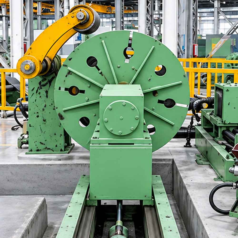
The mandrel is the core winding element. It is manufactured from high strength steel and is designed to hold the scrap coil securely during winding. Some designs include expandable or collapsible segments to facilitate coil removal.
Frame and Base
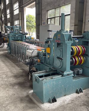
A rigid welded steel frame supports the mandrel and drive assembly. Adequate structural strength is required to resist the vibration and load generated by heavy gauge or high strength trim.
Drive System
An AC motor with gear reducer, torque motor, or variable frequency drive provides the winding power. Tension is controlled either electrically or through friction based devices such as slip clutches.
Scrap Guide and Deflector
Guide rolls, chutes, or deflectors direct the scrap strip toward the winder. They also prevent the trim from contacting the slitter knives or arbor shafts.
Scrap Loop Bridge or Pit
On many lines, a short loop section or pit buffers the scrap strip between the slitter head and the winder, compensating for minor speed variations.
Coil Discharge Device
Depending on the design, the finished scrap coil is removed by:
- Manual removal from an open end or cantilever mandrel
- Pneumatic or hydraulic pusher that ejects the coil
- Overhead crane or coil lifting equipment
- Tilting or rotating frame for double-mandrel designs
Control System
A control panel with start, stop, speed, and tension adjustment functions enables synchronized operation with the main line. Advanced configurations include PLC integration, coil diameter detection, and automatic alarm functions.
Types of Scrap Winding Machines
Single Mandrel Scrap Winder
This is the most common and economical configuration. The mandrel is typically cantilevered, allowing coils to be slid off manually or with a pusher. The line is briefly slowed or the trim is cut and redirected when changing coils.
Double Mandrel Scrap Winder
The double mandrel type features two winding positions, mounted on a rotating frame. When one coil is full, the machine indexes to the second mandrel, allowing continuous operation without stopping the line. It is suitable for high speed, high volume slitting lines.
Scrap Winder with Pusher
An integrated pneumatic or hydraulic pusher assists in removing finished coils from the mandrel, reducing manual labor and improving operator safety.
Scrap Chopper as an Alternative
For thin material or lines where continuous winding is not practical, a scrap chopper cuts the trim into short pieces that fall into a collection bin. However, for medium and heavy gauge material, a scrap winder remains the preferred solution because of its compact scrap coil and easier recycling.
Factors Affecting Scrap Winding Performance
- Synchronization with line speed. The winder must follow the main line speed accurately to avoid slack or excessive tension.
- Tension control stability. Excessive tension causes strip breakage, while insufficient tension results in loose coils.
- Material thickness and strength. Thicker and higher strength trim requires a more robust mandrel and drive system.
- Trim width variation. Wider trim strips create larger coil build-up and higher torque demand.
- Guide alignment. Poor guide alignment can cause the scrap to wander, overlap, or contact the slitter shafts.
- Coil diameter growth. As the coil diameter increases, speed or torque must be compensated to maintain constant tension.
Selection Criteria
When selecting a scrap winding machine for a slitting line, the following points should be considered:
- Material range: Define the minimum and maximum thickness and trim width to be wound.
- Line speed: The winder must match the maximum speed of the slitting line.
- Scrap coil capacity: Determine the required coil diameter and weight to suit handling and recycling facilities.
- Operation mode: Choose a single mandrel type for standard operation or a double mandrel type for continuous production.
- Drive and tension control: Select torque motor, frequency control, or clutch-based tension according to material and speed.
- Coil removal method: Assess whether manual, pneumatic, hydraulic, or crane assisted removal is most suitable.
- Safety features: Protective guards, emergency stops, and interlocks should be included.
- Integration: Confirm compatibility with the existing slitter head, loop pit, and line control system.
- Supplier capability: Evaluate engineering experience, installation support, and after sales service.
Installation Position in the Slitting Line
A typical slitting line layout is arranged as follows:
- Coil car
- Decoiler (uncoiler)
- Pinch roll and shear
- Leveling machine
- Loop pit or looping bridge
- Slitter head with circular knives
- Scrap winding machine (adjacent to the slitter head exit)
- Tension stand
- Recoiler
The scrap winding machine is positioned at the slitter head exit, where the edge trim is separated from the main strip. This location allows the trim to be directed immediately to the winder, preventing accumulation or interference with the finished strips.
Maintenance and Operation Recommendations
- Inspect the mandrel and expansion mechanism regularly for wear or deformation.
- Maintain lubrication of bearings, gearboxes, and drive components according to the schedule.
- Check clutch or torque motor settings to ensure stable tension.
- Keep scrap guides clean and aligned to prevent strip wandering.
- Remove finished coils promptly to avoid overloading the mandrel.
- Verify safety guards and emergency stops before each shift.
- Record winding parameters for different materials and thicknesses to ensure repeatable setups.
- Train operators on safe coil removal and tension adjustment procedures.
Applications
Scrap winding machines are widely used on slitting lines processing:
- Hot rolled and cold rolled steel coil
- Stainless steel coil
- Galvanized and galvalume coil
- Pre painted (PPGI/PPGL) coil
- Aluminum and aluminum alloy coil
- Copper and brass strip
- High strength steel (HSLA, AHSS)
These lines supply the automotive, construction, appliance, electrical, packaging, and transformer lamination industries.
Conclusion
A scrap winding machine is an essential component of a safe, productive, and clean slitting line. By continuously removing and winding edge trim into compact coils, it prevents tangling, protects equipment, improves operator safety, and simplifies scrap recycling. Selecting the correct mandrel configuration, drive type, and tension control system for the intended material range ensures stable, long term operation.
LotosSlitting supplies scrap winding machines engineered for integration with complete slitting line solutions. For specifications, configuration advice, or a customized quotation, please contact our engineering team.
FAQ :
A scrap winding machine is a take-up unit at the slitter head exit that continuously winds the cut edge trim into compact, manageable coils.
It is installed adjacent to the slitter head exit, where the edge trim is separated from the main strip.
Tension is maintained by a torque motor, a frequency drive, or a slip or magnetic powder clutch, depending on the machine design.
Coils are removed manually, by a pneumatic or hydraulic pusher, or with an overhead crane, depending on the machine design.
Protective guards, emergency stops, and interlocks should be fitted to protect operators during winding and coil removal.