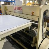
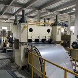
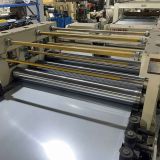
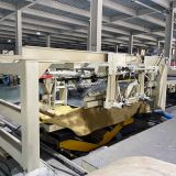
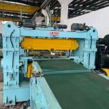
Cut to Length Lines (CTL) for Coil Processing
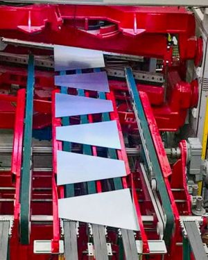
Designed for 0.5–4.0 mm × 2000 mm material, this machine is suitable for applications where stable feeding, reliable cutting, and accurate sheet stacking are important. Its 20 m/min working speed allows manufacturers to maintain a continuous production process while handling medium gauge materials efficiently. The line can be engineered according to different coil weights, material grades, sheet lengths, and production layouts, making it suitable for a wide range of metal processing applications.
Applications
The Medium Gauge Cut To Length Machine is suitable for producing accurately cut metal sheets for steel fabrication, construction, automotive components, electrical cabinets, industrial equipment, metal processing, and general manufacturing. It can process different coil materials and thicknesses while maintaining stable production performance and consistent sheet dimensions.
Working Flow :
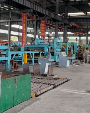
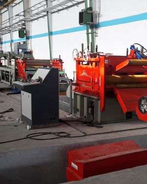
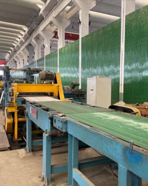
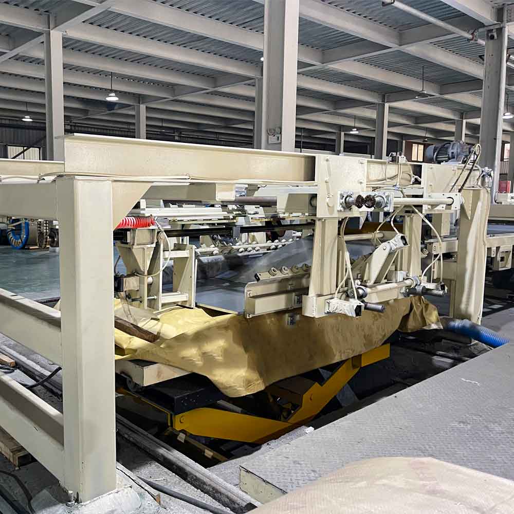
From right to left: Entry coil car → Paper collecting machine → Hydraulic cantilever decoiler → Straightening device → Film applicator → Looper lifting platform→ Side guide device → Feeding guide → Pneumatic clutch shearing unit → Conveyor → Stacker
Main Technical Proposal :
1.0 Hydraulic Cantilever Decoiler | ||
| 1.1 | Principle | Single-sided mandrel hydraulic expansion and contraction disc type |
| 1.2 | Shaft core surface | Special strength: hard chrome plating, chrome plating layer is 0.05mm- 0.10mm, bright surface |
| 1.3 | Shaft core diameter | Nominal diameter 508mm, 610mm rubber sleeve increased diameter |
| 1.4 | Shaft core slice number | 4 pcs |
| 1.5 | Shaft core length | 2100mm |
| 1.6 | Shaft core expansion and contraction scope | 470mm-520mm |
| 1.7 | Shaft core expansion and contraction | Rotary hydraulic joint, the joint is fixed and beautiful |
| 1.8 | Shaft drive | DC motor 37kw active unwinding |
| 1.9 | Shaft centering adjustment amount | ± 65mm |
| 1.10 | Shaft centering adjustment | Hydraulic cylinder TC150mm*130ST |
| 1.11 | Expansion and contraction cylinder | FA180mm × 100ST |
| 1.12 | Spindle | Made of forged SCM440 chromium molybdenum steel |
| 1.13 | Heat treatment process | Quenching and tempering. Surface high frequency quenching, grinding, hard chrome plating and polishing. |
| 1.14 | Rear sight | The reel has a scale. The overall movement has a scale. |
| 1.15 | Gears | Hard tooth surface (20CrMnTI) |
| 2.0 Unwinding Device | ||
| 2.1 | Structure type | Pressure roller pressing type |
| 2.2 | Press roller | Φ250mm× 460mmL (polyurethane rubber, slotted in the middle) |
| 2.3 | Roller lifting | Cylinder CA 80mmX 350mmSTX1 |
| 2.4 | Roller driven | Hydraulic motor |
| 2.5 | Remark | Cantilever fixed on the base of the uncoiler for unwinding the coil material |
| 3.0 Shovel feeder+Feeding rollers | ||
| 3.1 | Structure type | The front end of the feeding device is telescopic and swings up and down, and is fixed on the straightening body. |
| 3.2 | Swing up and down | Hydraulic cylinder drive |
| 3.3 | Front-end scaling | Hydraulic cylinder drive |
| 3.4 | Material guide | Hard chrome plating |
| 3.5 | Linear slide rail | LGW30CB/1080mmL |
| 3.6 | Straight head device | Double hydraulic cylinder drive, with PU roller straight head |
| 3.7 | Remark | Installed at the pinch roller on the entry side of the straightener |
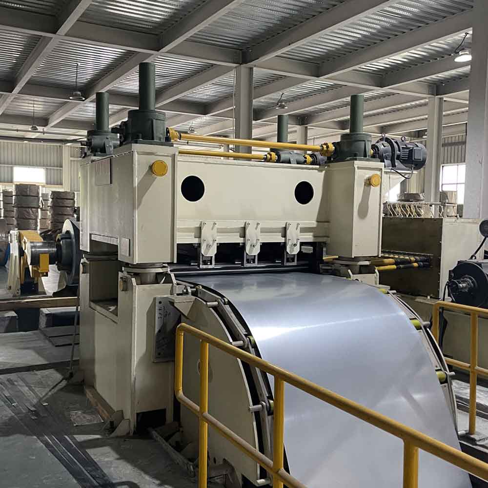
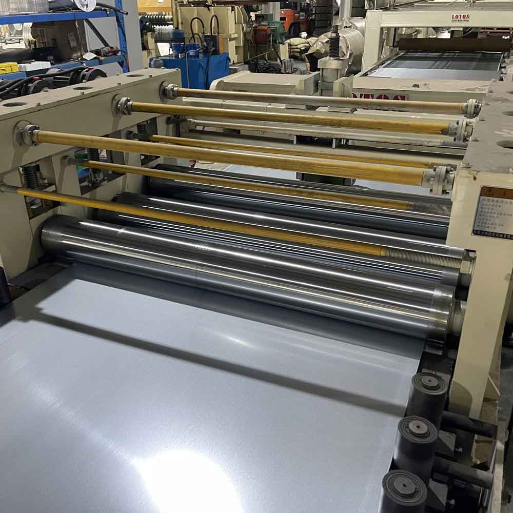
| 4.0- 4-layers leveling unit | ||
| 4.1 | Structure type | 19 straightening rollers, 4-layer type |
| 4.2 | Body frame | Steel plate structure, heat treated to eliminate stress, sand blasting |
| 4.3 | Transmission equipment | Sealed gearbox (with A.C 1.5KW circulating oil pump) |
| 4.4 | Gear material | 20CrMnTi (tempering and quenching, hard tooth surface, tooth surface grinding) |
| 4.5 | Work roller | Φ80mm |
| 4.7 | Support roller | Φ80mm ,Adopt three rows of support form |
| 4.9 | Motor power | 160KW |
| 4.10 | Roller surface lifting: | AC2.2KW X 1/25 X 2 sets, Frequency conversion, four screw lifters to adjust the position, with limit function |
| 4.11 | Brake | Pneumatic disc brake devices X 1 set |
| 5.0 Looper Lifting Platform | ||
| 5.1 | Type | The roller package is PU, and the transition platform is lifted by motor. |
| 5.2 | Size | 2200mmW× 4500mmL |
| 5.3 | Structure | The platform is welded from steel plates and square tubes, annealed and sandblasted. |
| 5.4 | Loading weight | 1000kg(Max) |
| 5.5 | Board structure | Welding and processing of steel plates and shaped steel, surfacecoated with nylon plates |
| 5.6 | Vertical roller material | Gcr15, surface quenching |
| 5.7 | Remark | Storage materials |
| 6.0 Side Guide Device | ||
| 6.1 | Type | Plumb vertical idler type |
| 6.2 | Function | Center the steel plate after passing through the leveler to avoid errors caused by deviation of the plate from the center. |
| 6.3 | Structure | Steel plate welded, stress relief annealed |
| 6.4 | Guide wheel | Gcr15, surface quenched and ground, φ 85*100 (3 pieces on one side, 6 pieces in total) |
| 6.5 | Adjustment method | Electric adjustment, one side can be adjusted, both sides can operate simultaneously |
| 7.0 Servo fixed length feeding | ||
| 7.1 | Type | The wheels are wrapped with rubber and are sent in between. |
| 7.2 | Side arm | CNC cutting, steel plate welding, annealing treatment, side wall thickness is 60mm. |
| 7.3 | Basement | 20mm steel plate and section steel are welded, annealed, and then sandblasted. |
| 7.4 | Gearbox gear | The gear box is welded and annealed, and the gears are hard tooth surface (20CrMnTI). |
| 7.5 | Feeding roller | 2 pieces, material: seamless tube, tempered, surface covered with high-quality polyurethane (φ280mm× 1950mmL). |
| 7.6 | Lifting method | The lower roller is fixed, the pneumatic cylinder drives the upper roller to rise and fall, and the synchronization gear ensures synchronization. |
| 7.7 | Lift cylinder | FA250× 50ST |
| specifications | ||
| 7.8 | Transmission way | The motor is connected to the roller through a timing belt. |
| 7.9 | Motor Power | Inovance 37KW servo motor |
| 7.10 | Remark | Configure the remote control to operate the movement of the tool holder to facilitate tool arrangement. |
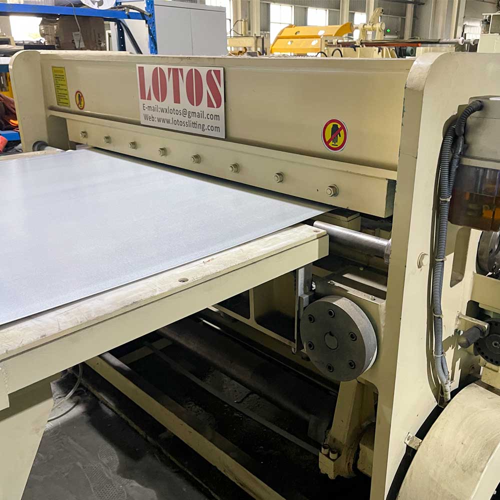
| 8.0 Pneumatic Clutch Shearing Device | ||
| 8.1 | Type | Use mature pneumatic clutch shearing machine and flywheel energy storage to reduce energy consumption. |
| 8.2 | Body frame | Steel plate and steel welding, annealing and sandblasting, CNC processing. |
| 8.3 | Cutting power | Provided by 30KW AC motor |
| 8.4 | Cutting method | Lower knife and upper cutting type |
| 8.5 | Cutting capacity | 1-8mm, blade width 1950mm |
| 8.6 | Cutting efficiency | Production speed is 60m/min(Max), shear frequency is 120Cut/Min(Max) |
| 8.7 | Feeding length | 250mm-6000mm |
| 8.8 | Lubrication method | Automatic oil pump |
| 8.9 | Blade material | SKD11, and high-strength blades |
| 8.10 | Blade hardness | HRC61 |
| 8.11 | Knife gap adjustment | Manual adjustment |
| 8.12 | Remark | 42crmo, forged, quenched, tempered |
FAQ :
A Medium Gauge Cut To Length Machine is a coil processing line designed to uncoil, level, feed, measure, cut, and stack metal coils into sheets with accurate and consistent dimensions.
Yes. The feeding and measuring system can be configured to produce sheets with different lengths according to the customer’s production requirements.
The Medium Gauge Cut To Length Machine can process coils with a maximum width of 2000 mm.
The machine is designed to process metal coils with a thickness range of 0.5–4.0 mm, depending on the material grade and machine configuration.