Design, Construction and Installation Guide
A cut to length (CTL) production line converts steel, stainless steel, aluminium or coated coils into flat sheets of precise length and flatness. While attention is usually focused on the decoiler, leveler, feeder and shear, the performance of the entire line ultimately rests on something far less visible: the foundation.
An inadequate foundation leads to misalignment, vibration, poor flatness, inaccurate cut lengths, premature bearing wear, and costly downtime. A properly engineered foundation, by contrast, preserves machine alignment for the life of the line and allows the equipment to deliver its rated accuracy and speed.
This article explains the principles, specifications and best practices for designing and constructing a reliable cut to length line foundation.
1. Why the Foundation Matters
The foundation of a cut to length line performs four essential functions:
- Load transfer – It carries the static weight of the machinery and coils, together with dynamic forces from shearing, levelling, and coil handling, and distributes them safely to the subsoil.
- Alignment stability – It keeps every machine section on a common centreline and elevation, which is critical for strip tracking and squareness of cut.
- Vibration damping – It absorbs and dissipates the impact energy produced by the shear and the cyclic loads from the leveler and feeder.
- Long term durability – It resists settlement, cracking, oil penetration and thermal movement over decades of operation.
Even a few tenths of a millimetre of differential settlement between the leveler and the shear can produce camber, diagonal error or length deviation in the finished sheet. For this reason, the foundation should be treated as an integral part of the machine rather than as ordinary building work.
2. Loads Acting on the Foundation
A structural engineer should design the foundation using load data provided by the equipment manufacturer. The principal load cases are:
2.1 Static Loads
- Self weight of each machine section
- Maximum coil weight on the decoiler mandrel and coil car
- Weight of finished sheet stacks on the stacker tables
- Weight of hydraulic units, electrical cabinets and auxiliary equipment
2.2 Dynamic Loads
- Shear impact forces, which depend on material thickness, tensile strength and cutting width
- Leveling forces generated by the work roll cassette
- Inertial loads from rapid acceleration and deceleration of the feeder and flying shear
- Braking torque reactions at the decoiler
2.3 Eccentric and Overturning Loads
The decoiler carries the coil on a cantilevered mandrel. The foundation block and anchor bolts must resist the resulting overturning moment without uplift or rocking.
2.4 Thermal and Environmental Loads
Long foundations are subject to temperature-induced expansion and contraction. Expansion joints must be positioned so that they never pass beneath a single machine frame.
3. Site and Soil Investigation
Before design begins, a geotechnical investigation should establish:
- Allowable bearing capacity of the soil
- Soil type and stratification (clay, sand, fill, rock)
- Groundwater level, which is especially important where looping pits or deep shear pits are required
- Settlement characteristics, including the risk of differential settlement
- Presence of fill material or old foundations that must be removed
Where soil bearing capacity is low or variable, soil improvement, a thicker raft, or piled foundations may be required. Under no circumstances should a precision coil processing line be placed directly on an ordinary industrial floor slab without verification.
4. Foundation Types and Layout
4.1 Continuous Raft (Mat) Foundation
A single reinforced concrete raft beneath the full length of the line is the preferred solution for most cut to length lines. Its advantages include:
- Uniform distribution of loads
- Minimal differential settlement between sections
- A common reference for alignment of all machines
4.2 Isolated Machine Foundations
Separate foundation blocks may be used for individual sections, particularly where:
- The shear must be isolated from the precision leveler and feeder to reduce vibration transfer
- The line is very long and a continuous raft is impractical
When using isolated blocks, fill the gap between them with a compressible joint material, and closely control the elevations.
4.3 Hybrid Arrangement
Many modern lines combine a raft for the entry and processing sections with an isolated, heavier block for the shear, giving both stability and vibration control.
4.4 Separation from the Building Floor
The machine foundation should be structurally separated from the surrounding workshop floor slab by an isolation joint. This prevents building movement and forklift traffic from disturbing machine alignment, and stops machine vibration from propagating into the building.
5. Pits, Trenches and Embedded Items
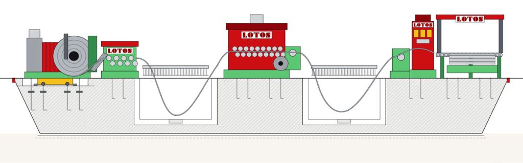
A typical cut to length line foundation includes several recessed and embedded elements:
- Coil car pit and rails – Rails must be level, parallel, and correctly gauged to the coil car wheels.
- Looping pit – Sized to the strip width and loop depth specified by the manufacturer, with drainage, a sump if required, and guarding or covers for operator safety.
- Scrap pit or scrap conveyor trench beneath the shear, where specified.
- Cable trenches – Separate trenches or conduits for power and control cables to reduce electrical interference, with removable covers.
- Hydraulic pipe trenches – Designed to contain oil leakage and allow inspection.
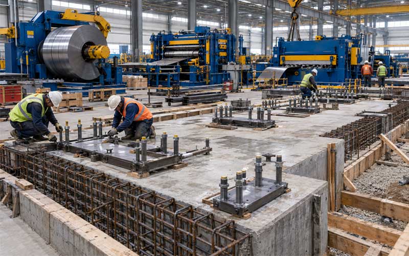
- Embedded plates and sleeves – Positioned accurately according to the foundation drawing before concrete placement.
All pits and trenches should be waterproofed where groundwater is present, and floors should slope towards drainage points.
6. Anchor Bolts and Base Plates
Anchor bolts secure the machinery to the foundation and resist uplift, sliding and overturning forces.
6.1 Anchor Bolt Methods
- Cast in anchor bolts – Set in position with a steel template before concrete placement. They offer high capacity but require very accurate setting.
- Anchor bolt pockets (block-outs) – Recesses are formed during the main pour. The bolts are placed after the machine is positioned and then grouted. This method allows adjustment and is common for coil processing equipment.
- Post-installed chemical or mechanical anchors – Suitable for lighter auxiliary equipment where approved by the engineer.
6.2 Good Practice
- Use bolt grades, diameters and embedment lengths specified on the manufacturer’s foundation drawing.
- Clean pockets thoroughly of dust, water and debris before grouting.
- Tighten anchor bolts to the specified torque only after the grout has achieved its required strength.
- Re check bolt torque after the initial operating period.
7. Levelling, Alignment and Grouting
7.1 Levelling
Machines are set on steel shims, wedges or levelling screws above the rough concrete surface. A precision machinist’s level, optical level or laser tracker is used to set elevation and level.
Typical tolerances for precision sections such as the leveler and feeder are in the range of 0.05–0.1 mm per metre, although the manufacturer’s installation manual is the governing reference.
7.2 Alignment
- A line centreline is established using piano wire, laser or total station and is permanently marked on the foundation.
- Each machine is aligned to this centreline and to a perpendicular reference for squareness.
- Roll parallelism between the leveler, feeder and shear is checked after alignment.
7.3 Grouting
The gap between the base plate and the concrete (commonly 25–50 mm) is filled with non-shrink grout:
- Cementitious non-shrink grout for general applications.
- Epoxy grout for areas of high dynamic load, vibration or oil exposure, such as beneath the shear and leveler.
The concrete surface should be roughened, cleaned, and pre wetted (for cementitious grout) before pouring. Grout must flow continuously from one side to eliminate air pockets.
8. Vibration Control
The shear is the main source of vibration in a cut to length line, particularly when processing thick or high strength material at high stroke rates. Vibration control measures include:
- Mass: Increasing the mass of the shear foundation block so that its natural frequency is well separated from the operating frequency.
- Isolation joints: Separating the shear block from the leveler and feeder foundations.
- Isolation pads: Elastomeric or spring isolators where specified by the manufacturer.
- Rigid anchorage: Ensuring that machinery is fully grouted, with no hollow areas beneath the base plates.
Effective vibration control protects both cut length accuracy and the service life of bearings, gears and servo drives.
9. Construction Sequence and Curing
A typical construction sequence is:
- Receipt and review of the manufacturer’s foundation drawing and load data
- Geotechnical investigation and structural design
- Setting out of line centreline and reference levels
- Excavation, compaction and lean concrete blinding
- Waterproofing of pits (where required)
- Fixing of reinforcement, formwork, anchor templates, pocket formers and embedded items
- Inspection and approval before concrete placement
- Concrete pouring and compaction
- Curing
- Survey of as-built dimensions and handover to the installation team
Curing
Concrete should be kept moist and protected from rapid drying for at least 7 days. Concrete typically reaches its design strength at 28 days. Heavy machinery should not be loaded onto the foundation until the engineer confirms that adequate strength has been achieved.
Conclusion
The foundation is the starting point for the accuracy, productivity, and service life of any cut to length production line. Careful attention to soil investigation, load analysis, concrete specification, anchor bolt placement, levelling, grouting and vibration control ensures that the line performs to its design specification from the first coil onward.
The most reliable results are achieved when the machine manufacturer, structural engineer and civil contractor work together from the earliest planning stage, using the manufacturer’s foundation drawing as the governing reference.
LOTOS supplies cut to length and slitting lines together with detailed foundation drawings and load data, and supports customers throughout planning, installation and commissioning. For foundation drawings or technical guidance on your project, please contact the LOTOS engineering team.
FAQ:
The foundation surface should typically be level within ±1-2 mm across the line, as uneven ground causes misalignment, vibration and inconsistent cut-to-length accuracy.
Thickness depends on coil weight, line speed and soil bearing capacity, but most lines need 300-500 mm of reinforced concrete under the decoiler, leveler and shear, with deeper isolated pads under heavy-duty equipment and a final design confirmed by a structural engineer.
The finished surface should be level to within about ±1-2 mm across each machine base, with grouting under the base plates, so the leveler rolls and shear blades stay parallel and the cut sheets keep tight length and squareness tolerances.
Allow at least 7 days before positioning light equipment and the full 28 days before the leveler and shear are fixed and operated under load, to ensure the concrete reaches its design strength.
A weak or uneven foundation causes vibration, shifting alignment, uneven leveling, inaccurate cut lengths, premature bearing and blade wear and costly downtime for re-grouting and recalibration.